![]() Neuron Power Engineer is using the expressions "negate" and "negation". You might know this as "invert" and/or "inverting".
Neuron Power Engineer is using the expressions "negate" and "negation". You might know this as "invert" and/or "inverting".
How to toggle the negating behavior of an in-/output in the →graphical FBD-editor:
-
Select one or several inputs/output of an FBD-element (e.g. a →call of a →block or a →value field containing a →variable) by clicking onto the in-/outputs while pressing and holding the Ctrl-key.
Negations are only possible for shown in-/outputs of the →generic data typeANY_BIT. You are not able to negate in-/outputs of other types. -
From the context menu of the FBD-editor, select Negate In-/Output. Alternative: Press the i-key or double-click.
Result: The in-/output is negated. But if it has already been negated, the negation is removed.
Negated inputs and outputs are represented by small circles around the respective in-/output. The color of this circle is determined by the data type that is assigned to the in-/output.
Example: The input IN1 of the function call MyFun is negated.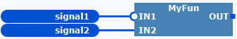
|
Notes and restrictions
|
Examples for the behavior of negated inputs
![]() The following examples illustrate the behavior for →functions. Observe that the same behavior is valid for →function blocks as well.
The following examples illustrate the behavior for →functions. Observe that the same behavior is valid for →function blocks as well.
Initial scenario 1
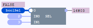
The value of the Boolean input G of the SEL function determines whether the function returns the value of the input IN0 or IN1: In case of FALSE, the function returns the value of IN0.

Example 1.1: By negating the input G, the value FALSE of the variable boolSel is negated. Hence, value TRUE is valid for the input G. In case of TRUE, the function returns the value of IN1.
Example 1.2: If the input G is unconnected and negated, the default →initial value FALSE of BOOL is negated. Hence, the value TRUE is again valid for the input G. As in example 1, the function returns the value of IN1.
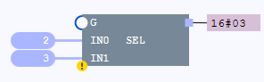
The icon for the function call indicates that the call is causing a warning. In particular, the warning is caused by the negated input to which no other element is connected,
Initial scenario 2
The user-defined function assigns the value of the input IN1 to the output OUT1.
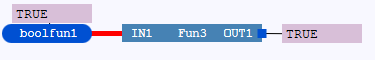
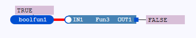
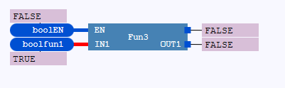
Example 2.1: By negating the input IN1, the value FRUE of the variable boolFunl is negated. Hence, the value FALSE is valid for the input IN1 and assigned to the output OUT1.
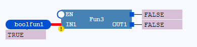
Example 2.1: If the input IN1 is unconnected and negated, the initial value TRUE of the input IN1 (as specified in the function) is negated. Hence, the value FALSE is again valid for the input IN1. As in example 2.1, the value FALSE is assigned to the output OUT1.
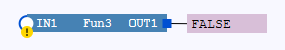
The icon for the function call indicates that the call is causing a warning. In particular, the warning is caused by the negated input to which no other element is connected,
Initial scenario 3
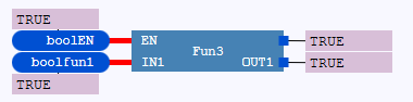
The value of the input EN of the user-defined function (from example 2) control the execution of the function.
See "Execution control: EN, ENO" for details on the behavior. Here a short summary:
|
In case of
|
Connected
Unconnected
|
|
In case of |
Connected
|
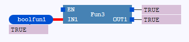
Example 3.1: If the input EN is unconnected and negated, the preset default value TRUE for EN is negated. Hence, the value FALSE is valid for the input EN. Subsequently, the functionality of the function is not executed and the output ENO is reset to FALSE.
The icon for the function call indicates that the call is causing a warning. In particular, the warning is caused by the negated input EN to which no other element is connected,